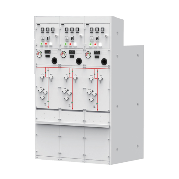
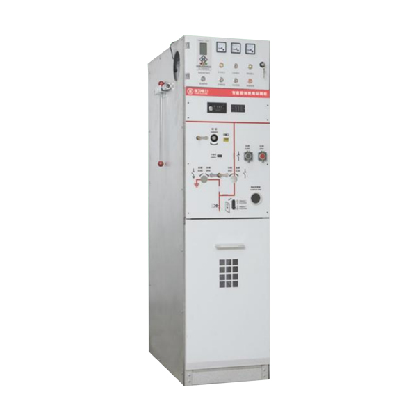
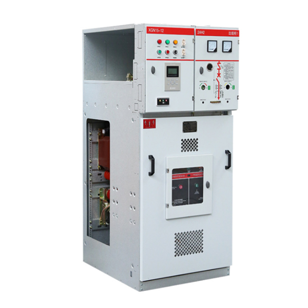
Modular AC metal enclosed Ring main unit RMU
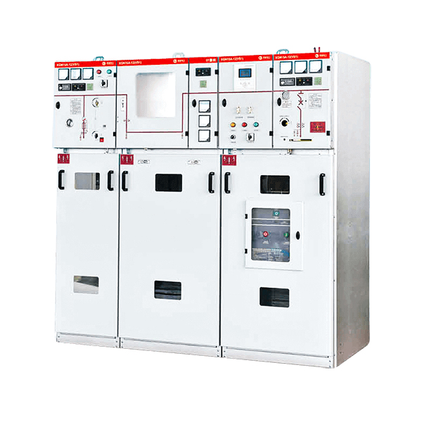
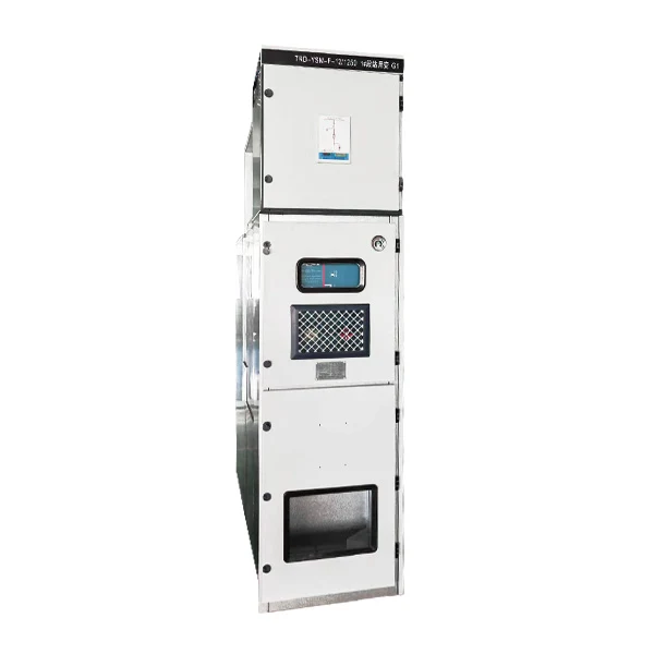
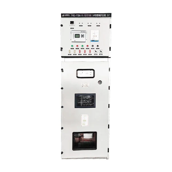
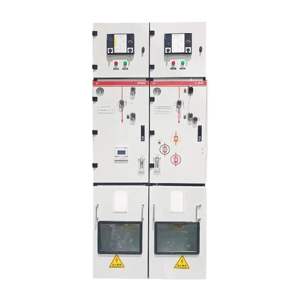
HXGN-12 switchgear Modular AC metal enclosed Ring main unit RMU is a high-voltage AC complete set designed for a three-phase AC ring network, terminal distribution network, and industrial electrical equipment. It is suitable for power distribution and protection and can be installed in substations. It complies with national standards GB3906 and IEC60298, as well as DL/T402 and DL/T404 standards, and meets the requirements of "five-proof" blocking.
Model:HXGN-12
Send Inquiry
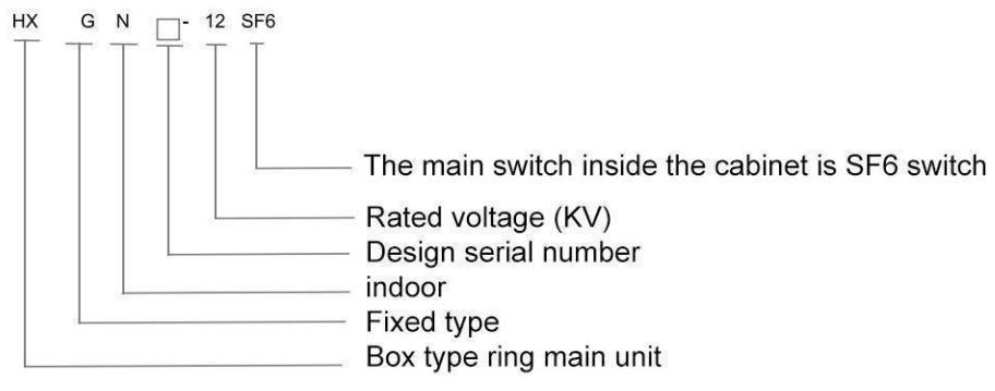
Model meanings
Working conditions of Modular AC metal enclosed Ring main unit RMU
◆ Environmental temperature: upper limit+40 ℃, lower limit -25 ℃;
◆ Altitude: The altitude does not exceed 2000m;
◆ Relative temperature: The daily average value shall not exceed 95%; Monthly average not exceeding 92%.
◆ Surrounding environment: The surrounding air is not significantly polluted by corrosive gases, flammable gases,water vapor, etc.,
◆ There is no frequent violent vibration.
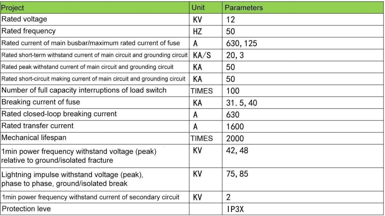
Technical Parameters of Modular AC metal enclosed Ring main unit RMU
Structural characteristics
◆ Cabinet characteristics
◇The Modular AC metal enclosed Ring main unit RMU shell is formed by riveting 2mm thick aluminum zinc sheet (or cold-rolled sheet sprayedwith plastic), and there are two pressure release holes at the back of the cabinet, one for the cable compartment and the other for the load switch/busbar compartment. This structure can maximize the reliability of personal installation and operation of equipment.
◆ Each compartment
◇ Busbar room:The busbar room is located at the top of the cabinet and connected to adjacent switchgear.
◇ The load switch is an independent unit filled with SF6 gas.
◇ Cable room: Approximately 75% of the space is used for cable connections, fuses, grounding switches, and installation of PT and CT.
◇ Mechanism Room and Interlocking: The room includes operating mechanisms and mechanism interlocks, as well as position indications, auxiliary contacts, trip coils, live displays, and interlocks.
◇ Low voltage box: The low voltage box is located at the top of the cabinet and is optional. The small room is used to install special devices such as instruments/relays and motor units.
◇ Circuit breaker room: A circuit breaker (SF6 or vacuum) can be placed below the load switch.
◆ Pressure release:
◇ Pressure release above: The above is used to release the gas pressure generated during arc accidents inside the busbar and load switch room.
◇ The pressure release below is used to release the gas pressure generated during an arc accident inside the cable compartment.

Overall dimension

Technical parameters


This switch has many advantages:
◇ The duration of the arc is short, and the insulation strength in the arc extinguishing chamber recovers quickly.
◇ Ensure safety and reliability even in the most demanding environments.
◇ Can disconnect low value inductive and capacitive currents.
◇ The operating mechanism is simple, can quickly open and close, and has a long mechanical life.
◇ Reduced the loss of contacts and arc extinguishing chambers, and also extended the electrical life.
◇ Allow for multiple operations, but with minimal maintenance workload.
◇ Lightweight structure, compact and stable.

Base Components
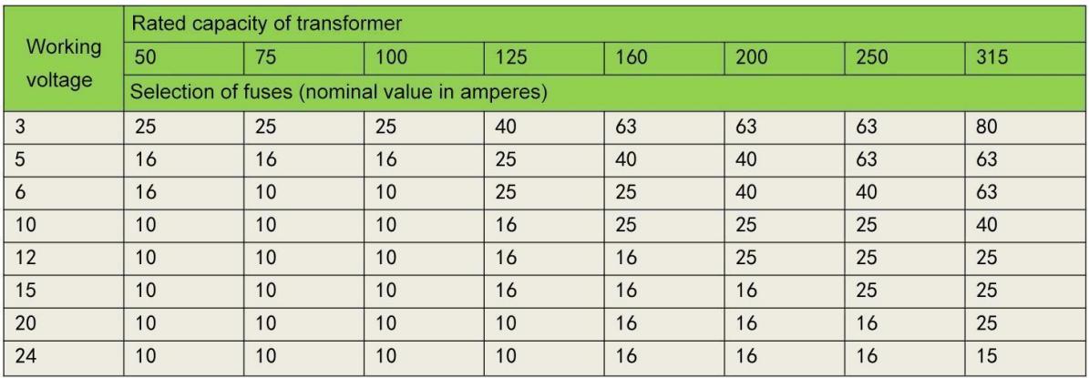

◆ SFL-12/24 switchgear
◇ The main components of SFL-12/24 switchgear are imported original parts. The switchgear is a dual port, three station, rotating moving contact, and uses SF6 gas as the arc extinguishing medium. The moving contact is placed in a die cast epoxy resin shell with a reinforced structure.
◇ Each switch is permanently sealed after being filled with SF6 gas at a pressure of 0.4 bars, and a helium detector can be used to detect any gas leakage. The switch is installed vertically and horizontally without limitation. A typical installation method in the ring main unit is to place a steel plate between the cable room and the busbar room and install it horizontally. This installation method isolates the busbar from the cable joints to meet the strictest safety requirements for operation and maintenance.
◇ If an internal arc occurs, there is a structural weakness at the back of the shell that will be pushed open, and then the arc valve on top of the cabinet will open and guide the overpressure airflow outside the cabinet.
Operating
For switch equipment equipped with load switches, a dedicated operating handle is used to operate on the front of the switch equipment. There are two operating holes on the front of the operating mechanism, the upper part is the grounding switch operating hole, and the lower part is the load switch operating hole. When operating, the handle rotates clockwise to switch, and the closing direction rotates counterclockwise to switch opening direction. Electric opening and closing devices can also be strengthened for remote control operation. (Note: Sometimes the load switch does not come with a grounding switch, and the operating hole of the grounding switch is used to unlock the cabinet door.). For switchgear with combined electrical appliances, except for the manual opening button of the load switch opening operation, the operation sequence is the same as above. The lower grounding switch installed in the combination electrical cabinet is connected and disconnected with the upper grounding switch through a connecting rod. Release the residual small current on the fuse holder when closing to improve safety when replacing the circuit breaker.
Appearance and installation dimensions

Ordering Instructions
The following information is required when placing an order:
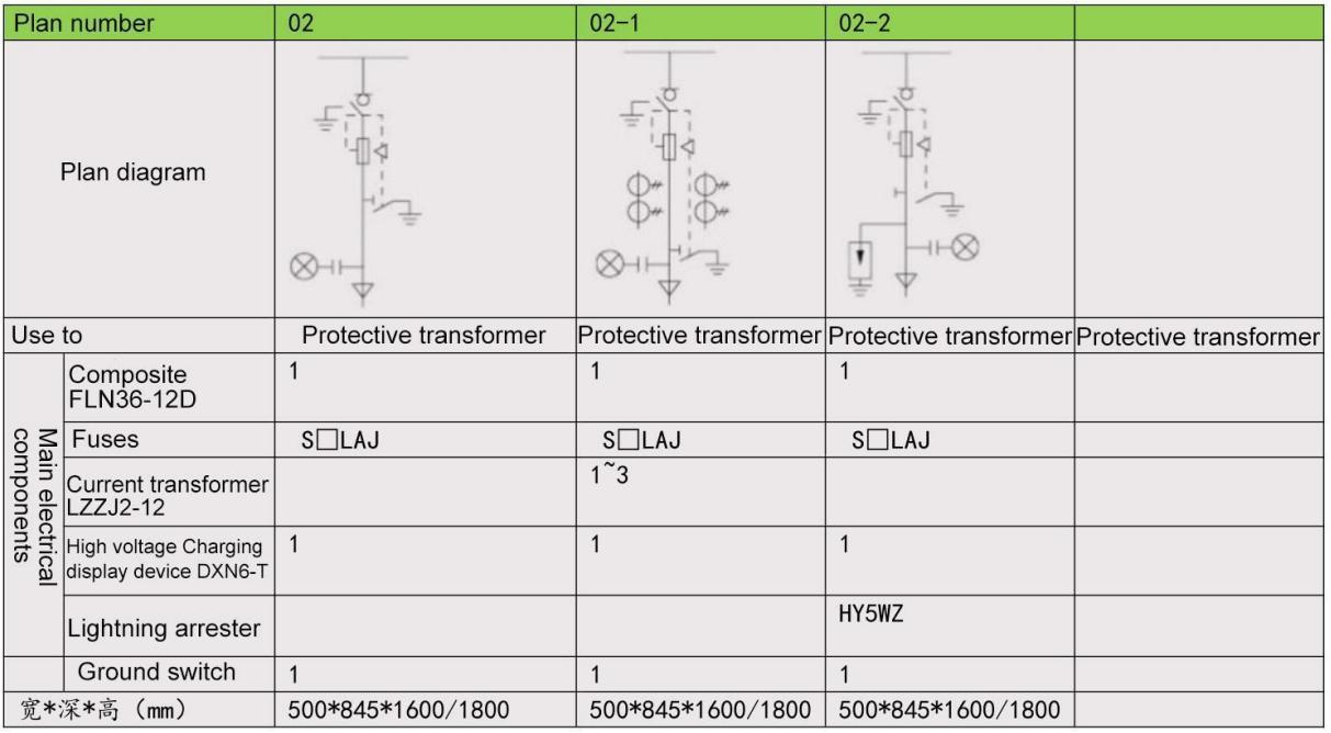
◆ Main circuit scheme number, main wiring system diagram, arrangement diagram, and layout plan:
◆ The model, specifications, and quantity of electrical components inside the switchgear;
◆ Name and quantity of spare parts;
◆ If there are special requirements, please consult with our company.
Main electrogram scheme diagram



Interlocks
The switchgear has the following interlocks:
◆ When the load switch is in the closed position, the operation of the grounding switch is locked;
◆ When the grounding switch is in the closed position, the load switch operation is locked;
◆ Only when the grounding switch is closed, can the front door of the ring main unit be opened. In other cases, the front door is locked.


