
Home > Products > Switchgear > Gas insulated switchgear > Outdoor high-voltage SF6 open type combination electrical appliances

Outdoor high-voltage SF6 open type combination electrical appliances
ZCW10-40.5G /T1600-31.5 Outdoor high-voltage SF6 open type combination electrical appliances is a complete set of units using air as external insulation SF 6 gas as arc extinguishing medium Combined electrical appliances.The control and protection of the three-phase AC 40.5kV transmission anddistribution system can also be used to connect circuit breakers and open and close capacitor banks.Suitable for the land shortage of urban substation, enterprise substation, mountain substation.
Model:ZCW10-40.5G/T1600-31.5
Send Inquiry
Product Description
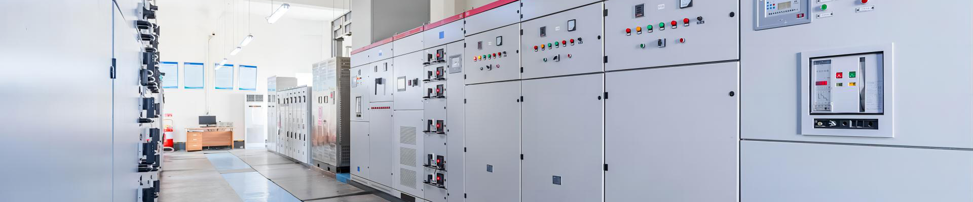
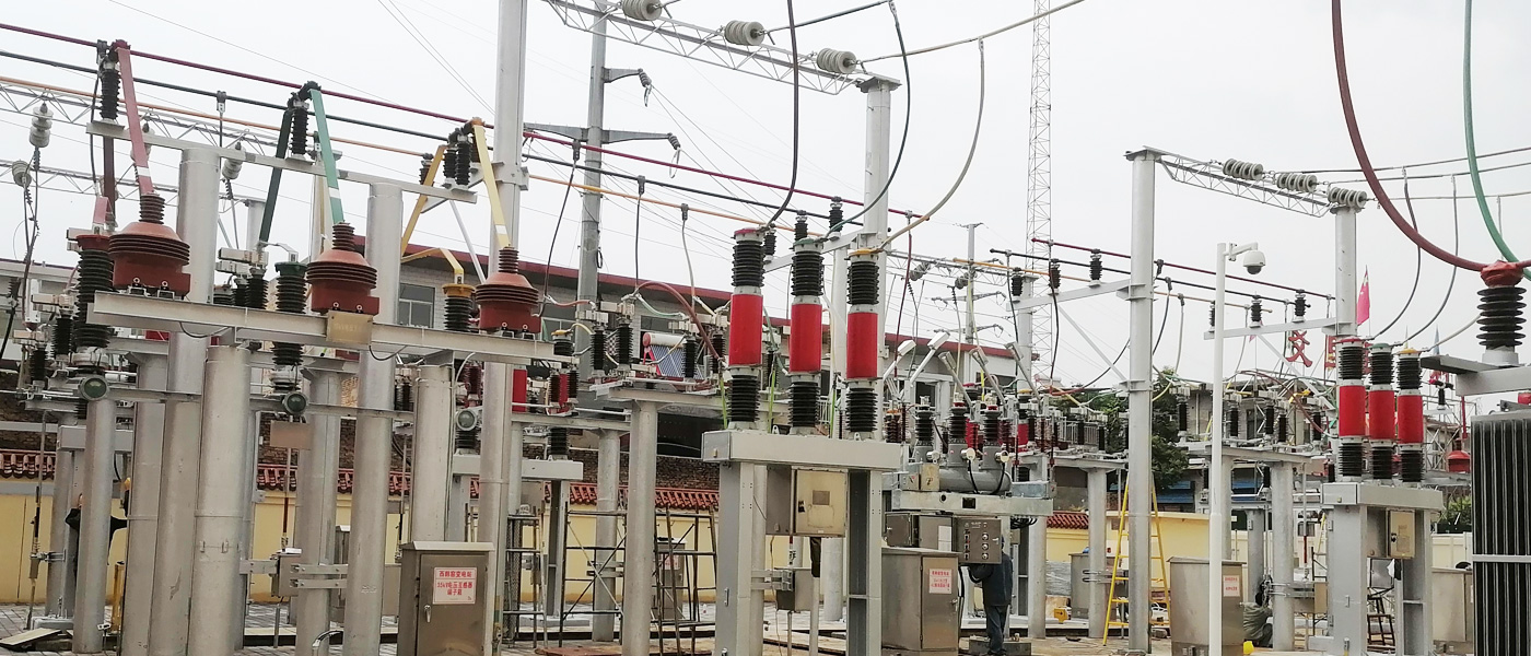
Installation Site
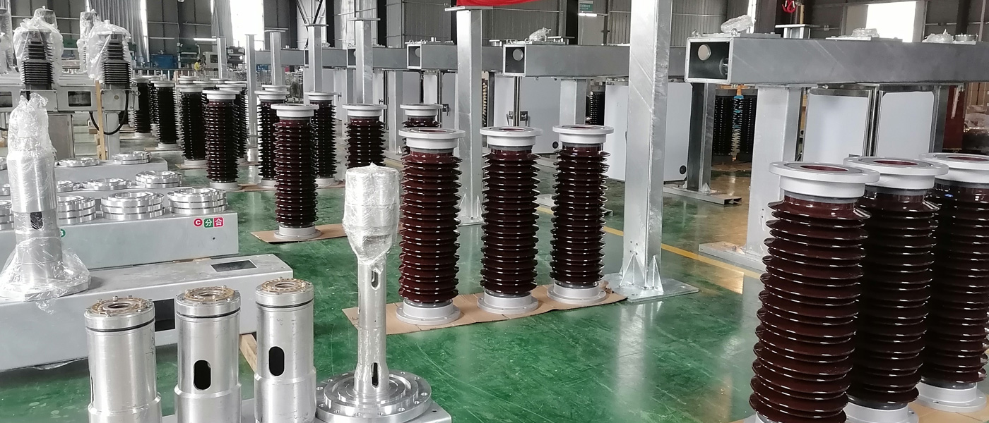
Workshop
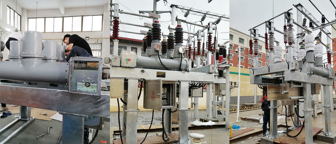
Product show
package
Overview
1.1 ZCW10-40.5G /T1600-31.5 Outdoor high-voltage Open-Type combination electrical appliance is a complete set of units using air as external insulation SF 6 gas as arc extinguishing medium Combined electrical appliances.
The control and protection of the three-phase AC 40.5kV transmission anddistribution system can also be used to connect circuit breakers and open and close capacitor banks.
Suitable for the land shortage of urban substation, enterprise substation, mountain substation.
The product has the following characteristics:
1) Combine the circuit breaker, disconnecting switch, grounding switch, current transformer, SF6 potential transformer, lightning arrester, busbar and other components organically on the grounded steel structure bracket, the structure is compact.
2) Its space is only 30% -50% of the split type, which has remarkable characteristics such as saving land and reducing project cost.
3) The entire interval factory is prefabricated, assembled and all commissioning before leaving the factory, and transported to the installation site, greatly shortening the installation cycle.
4) Adopt a new generation of high performance arc extinguishing chamber, SF6 voltage transformer, composite insulator lightning arrester, basically no maintenance, high reliability.
5) interval prefabricated self-support bus, without steel frame and insulator.
6) Flexible layout, which can be used for various wiring modes.
1.2 ZCW10 Equipped with optimized self-energy arc extinguishing chamber and CT10-A spring operating mechanism.
1.3 ZCW 10 Implement the national standards GB 1984-2003, GB 11032-89, GB 1985-2004, and meet the standards of the International Electrotechnical Commission
Requirements for IEC 62271-100:2001, IEC99-4 and IEC62271-102:2002 and IEC60694:2002. Other elements are installed inside it,All meet their respective national standard requirements.
Working conditions
2.1 This product is an outdoor product and can also be used in the home.
Use the environmental Conditions including:
a . Altitude : no more than 2,000 meters.
b . Ambient temperature : -30℃ - + 40℃ (special requirement-40℃ - + 40℃).
c . Relative humidity : daily average is not more than 95%, monthly average is not more than 90% (25℃).
d . Wind speed : not more than 35 m / s.
e . Grade IV, the climbing distance of porcelain sleeve is greater than 1450mm (nominal creepage distance is greater than 31mm / kV).
f . No flammable, explosive, chemical corrosion and violent vibration occasions.
g . Seismic intensity : no more than 8 degrees.
h . The ice-walking thickness is not greater than 10mm.
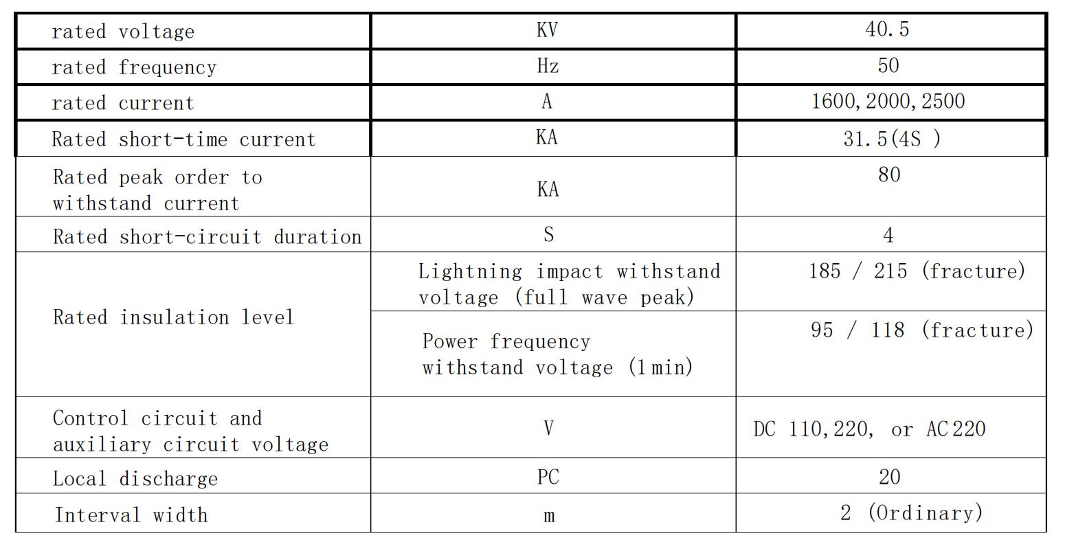
3. ZCW10-40.5G Main technical parameters are shown in Table 1 :
Table1
3.1 Circuit breaker parameters
Table2

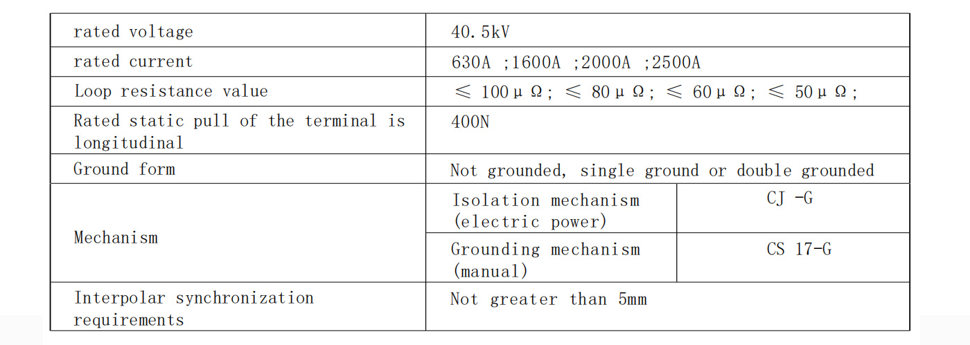
3.2 Disconnecting switch parameters
Table3
3.3 Current transformer
Accuracy level and the corresponding load
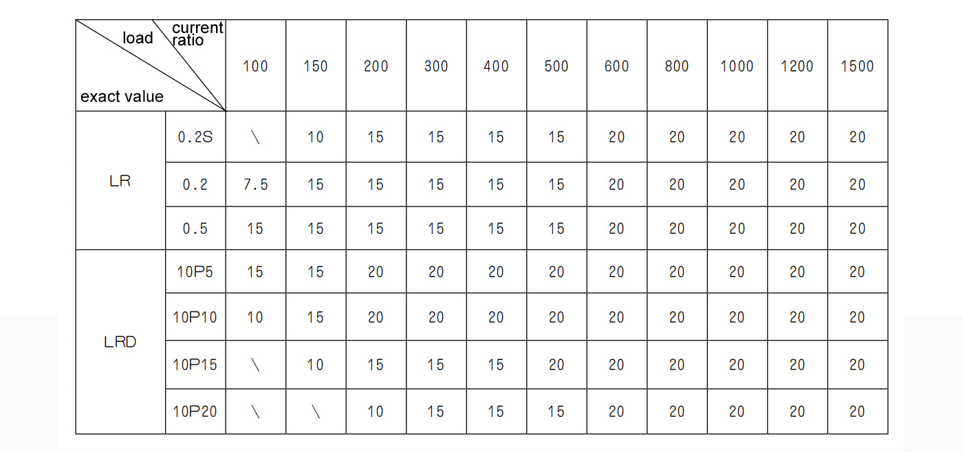
Note :
(1) The LR type and the LRD type are the current transformer for measurement and the
current transformer for protection.
(2) The transformer attached to this product is a central tube-type current transformer.
(3) The factory can design and manufacture special CT according to user requirements, and
various specific technical parameters can be solved through negotiation.
(4) When ordering, the specifications and models, current ratio, accuracy level, rated load and other parameters of the transformer must be indicated. If not indicated, according to the factory standard Supply of the current transformer.
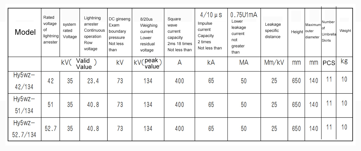
3.4 Arrester (power station type) parameters
Table6
3.5 Voltage transformer
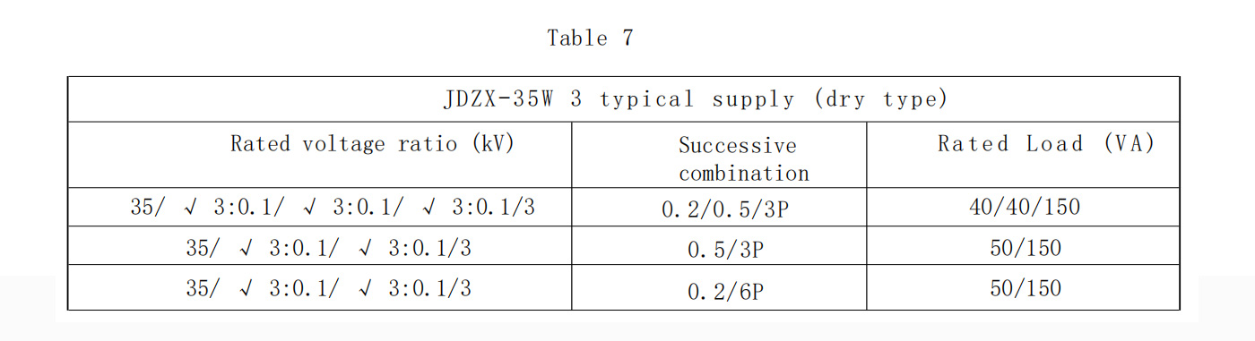
Note:
1. Load power factor is 0.8 (lag)
2. The exact level and rated output in the table can be combined differently according to the data in the table. The specific data is shown in the product nameplate. When the secondary winding outputs two accurate levels, the load is reduced to 25VA.
4. Structure and working principle
4.1 Overall structure of the ZCW10
ZCW10 Generally including the line interval, bus link and outlet interval, it can according to the different requirements of users of single bus, single bus segment, double bus and bridge wiring and other different wiring modes.
In this product, there is generally a local control Switchgear, and the secondary parts such as the gas monitoring device and the control loop of each element are concentrated inthe control switchgear.
4.2 Structure of the components
4.2.1 Circuit breaker
4.2.1.1 Overall structure.
The circuit breaker is a phase-tank structure, Three-phase share a spring operating mechanism, mechanical connection.
4.2.1.2 Principle of unipolar structure
The dynamic and static contacts are supported by insulators at both ends of the tank,and the dynamic contacts are connected with the switch spring through the insulation pull rod. The arc extinguishing chamber adopts a new generation of mixed-pressure arc extinguishing chamber, which integrates the advantages of self-energy type and compressor type.During the switch operation, the insulation pull rod is pulled by the switch spring, so that the moving contact, pressure cylinder, moving arc contact and nozzle can move quickly downward together. First, the moving contact is separated from the static contact, and then the moving arc contact is separated from the static arc contact to produce an arc, heating the SF6 gas in the gas room, so that the temperature increases, the gas pressure increases, at the same time, the piston compression gas room gas, the pressure further increases, the current over zero to produce strong air blowing to extinguish the arc. After the arc is extinguished, the strength of the break medium is quickly restored, and the moving contact continues to move downward to complete the switching operation.
During the closing operation, driven by the closing spring, the insulation pull rod moves upward to push the moving contact, pressure cylinder and other moving parts upward. At this time, SF6 gas quickly enters the pressure cylinder. During the closing operation, the pre-breakdown arc burns on the arc contact, the moving contact continues to move upward, the dynamic and static arc contact is first connected, the arc disappears, and the closing operation is completed. In this process, the brake spring is stored at the same time.
4.2.1.3 spring operating mechanism
The structure and operation principle of the spring operating mechanism
a.The energy storage process is as follows :
The eccentric wheel 1 driven by the motor rotates in the direction shown in the drawing and pushes the operation block 3 close to the surface of the eccentric wheel,Thus driving the driving pawl 5 to move up and down, and pushing the ratchet 7 to rotate in the direction shown in the figure. The ratchet and energy storage shaft 8 are empty, so at the beginning of energy storage,The energy storage motor drives the ratchet idling. When turning to the pin 12 fixed to the ratchet and the drive plate 10 fixed on the energy storage shaft, the ratchet passes The drive plate drives the energy storage shaft to rotate in the direction according to the arrow shown in the figure. The spring arm 14 is connected to the energy storage shaft, and the rotation of the energy storage shaft drives the spring arm Also rotate in the arrow direction to lengthen the closing spring 15. When the energy storage shaft turns to the highest position of the hanging spring turning arm, just a point forward (About 3 °), the energy storage shaft will be driven by the closing spring, and the roller 13 fixed on the cam connected with the energy storage shaft is close on In the positioning part, maintain the energy storage state of the closing spring to complete the energy storage action. At the same time, the hanging spring turns the arm through the line The range switch cuts off the power supply of the energy storage motor. On the other hand, the drive plate is also pushed away by the leaning plate 6 on the drive paw, which raises the drive paw to ensure the drive spine The claw is reliably separated from the ratchet so that the motor cannot stop or destroy it due to inertial movement.
b. closing operation :
FIGURE. 4 is a schematic diagram of the mechanism closing operation, and FIG. 4a shows the position of the closing operating system when the energy storage is maintained. The solid line indicates that the mechanism is in the switch, The position of the system at the storage position ; the double point line indicates the position of the system during the closed storage. FIG. 4b shows that the operating system performs the closing operation status after the making.
The closing operation process is as follows:
1 : Closing electromagnet operation : after the mechanism accepts the closing signal, the moving core of the closing electromagnet 1 is moved under the suction movement, and the pull guide plate 2 is also pulled downward movement rotates the lever 3 in the anticlockwise direction, and the rotation of the lever 3 drives the roller 7 fixed to the positioning member 6 and pushes the positioning member 6 to do clockwise rotation will remove the energy storage maintenance and complete the closing operation. When the mechanism is in the closing position, the linkage plate 8 is driven upward by the reset spring 9,
The slot on the chain board will block the roller 7, so that the positioning parts can not rotate clockwise, to achieve the purpose of the mechanism chain can also ensure that the mechanism is in the closing position no reclosing operation cannot be implemented.
2 : Manual button operation :
push the closing button installed on the panel push the button plate 5,and push the positioning part 6 by adjusting the screw turn clockwise to complete the closing operation.
C. Openning Operation
The switching operation of the mechanism
1 : The process of hand breaking is as follows : Fig. 5a shows that the mechanism is at the position of the fan plate 2 and the half shaft 3 in the closing position, and when it is pressed by hand When the switch connecting rod 1 is moved, the tripping plate 4 on the fixed half shaft is moved upward thus driving the rotation of the direction shown in FIG. 5b When the shaft turns to a certain position, the connection between the fan plate and the half shaft is lifted, the fan plate rotates in the direction of the arrow, and the mechanism is completed.
2 : The switch operation process of overcurrent tripping electromagnet and switch electromagnet is as follows :
When the mechanism is in the closed state, see FIG. 6a and the lock 11 are held at the lap point, the energy storage spring 7 is elongated, and the half shaft 1 is closed The gate position. Once the outrigger receives the switch signal, either core drives the top bar to push the button plate 2 to rotate clockwise drive lock 11 to rotate counterclockwise to remove the lap between lock 11 and lock 8. The lock 8 is
then driven by the energy storage spring 7 Counterclockwise rotation, through the pull rod to push the half shaft for clockwise rotation, so as to complete the switch operation. Figure 6b The system mechanism is in the switch state.
4.2.2 Disconnectingswitch and groundswitch
a :Disconnecting switch
The disconnecting switch is slow isolation, three connected, with motor operating mechanism.
b : earth switch
This grounding switch is a working grounding switch, equipped with CS 17-G manual operating mechanism.
C : There is electrical linkage between the disconnecting switch and the circuit breaker, and mechanical linkage between the grounding switch and the disconnecting switch to prevent misoperation.
D : The motor operating mechanism of the disconnecting switch is composed of the motor, transmission mechanism, micro switch and auxiliary switch. It is carried out by electric motorsThe worm rod and worm wheel are rotated to realize the disconnecting switch through the connecting rod system.
4.2.3. Current transformer
Current transformer is the power measurement and protection element in the product. It should be noted that in the use of the secondary loop is absolutely not allowed to open circuit, otherwise it will produce high pressure and cause equipment damage.
4.2.4. Potential transformer
This product adopts JDQX-35 type SF6 voltage transformer, and the parameters are shown in Table 7.
4.2.5 Lightning arrester
The arrester of this product adopts organic composite coat metal oxide arrester, and the parameters are shown in Table 6. The lightning arrester is a replacement product of the original porcelain type products, which can delay the impact force to avoid the explosion, and prevent the occurrence of malignant accidents affecting the other equipment and personal safety, and has good explosion-proof performance.
4.2.6 Bus bar
The aluminum hard bus produced by the manufacturer is used between the interval and the interval, which is provided by the user.
4.2.7. Control switchgear (exchange control switchgear)
The control switchgear is a centralized control screen for the field monitoring and control of the ZCW 10. Generally, it has the functions of local operation, signal transmission, protection, relay and monitoring of SF6 system. The main functions are shown as follows :
A : Implement the local-remote selection operation of the high voltage switch and conduct localoperation on the control cabinet.
B : Monitor the position status of the high voltage switch.
C : monitor whether the SF6 gas density in each element is in a normal state.
D : realize electrical linkage between switching elements and electrical linkage between switching elements.
E : Display the primary main wiring form and operation status.
F : As the intermediate terminal box between the main control room, receive or send signals.
G : Monitor whether the power supply of the control loop is normal, and monitor and protect the secondary control system through the power switch, fuse and protection switch.
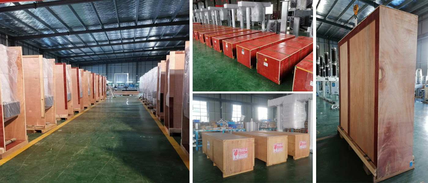
5. Packaging, transportation, and storage
A : ZCW 10 After qualified commissioning, it can generally be packaged and transported at intervals as a unit.
B : The front air chamber is generally filled with 0.02-0.05Mpa SF6 gas and adsorbent to prevent dust and moisture from entering.
C : each engineering equipment consists of several packaging and transportation units.Comprehensive inspection according to the packing list before delivery.
D : severe vibration shall be avoided during transportation and handling to prevent damage inside the equipment.
E : The product shall be stored in and without strong vibration at the site.
6. Installation and debugging
6.1 Installation
6.1.1 Preparation for installation
A : Check whether the ground and foundation construction of the installation site meets the drawing requirements according to the foundation drawing provided by the manufacturer or the design company.
B : The user shall provide the necessary equipment support, such as the 5T crane, etc.
C. : Check whether the parameters of the product nameplate meet the requirements of the technical agreement.
6.1.2 Installation
A : After each interval is in place, check the level of the circuit breaker. If uneven, an adjustment pad can be added between the bracket and the base for leveling.
B : tighten the busbar according to the drawing, and check that it is correct.
C : feed the SF6 voltage transformer and circuit breaker. No heavy vacuum is required.
6.2 Debug
6.2.1 Inspection work before commissioning
1 : appearance inspection
Mainly check the feet, fastening, grounding system, and the sulfur hexafluoride gas pressure indicated by the instrument.
2 : Wiring inspection
The wiring from the control cabinet to the operating system, and the terminal box of the current transformer, voltage transformer and other components must meet the requirements of the drawings.
6.2.2 Mechanical operation and mechanical characteristics test
1 : Mechanical operation and characteristic test of the circuit breaker
Store the mechanism to the specified value, operate twice, should have no abnormal phenomenon, and then do the mechanical characteristics experiment.
2 : Mechanical operation experiment of disconnecting switch and grounding switch
Open and close the disconnecting switch and the ground switch twice respectively, and there should be no abnormal phenomenon. In order to prevent electrical locking failure and cause accidents, manual operation of the disconnector is only allowed in debugging or emergency situations, and only electric operation in normal operation.
The isolation contact shall meet the dimensional requirements shown in Figure 4, and the static distance shall meet 500mm.
figure4

3 : Chain check
The circuit breaker is in the closed position, and the isolation switch should be electric and inactive. When the isolating switch is in the closed position, the ground switch should not act.
6.2.3 Resistance measurement of the main loop
The resistance measurement of the main loop shall be conducted between the terminals of the inlet and outlet line or the grounding switch. The measurement method shall be the same as the measurement method in the factory, and the resistance value shall not exceed the specified value.
6.2.4 Resistance measurement of the breaker main circuit
Measure the breaker main circuit to ground insulation resistance shall be greater than 1000 megohm with a 1000V shake table. The insulation resistance of the auxiliary circuits and control circuits shall be greater than 2 megohms.
6.2.5 SF6 Gas moisture content measurement
The moisture content of the new sulfur hexafluoride gas in the gas cylinder shall not be greater than 8 μ L / L (v / v), and the moisture content of the sulfur hexafluoride in the equipment shall be measured 24 hours after the gas filling, and shall not be greater than 150 μ L / L.
6.2.6 Leakage test
The sensitivity is not less than 10-8The SF 6 gas collector checks the air tightness of all the sealed connections. The leak detection method can be the local dressing method,Annual air leakage rate should not be greater than 0.3%.
6.2.7 Electrical linkage test of circuit breaker and disconnector
The circuit breaker, disconnecting switch and grounding switch of the same unit must meet the interlocking conditions specified in the electrical control schematic diagram.
6.2.8 Power frequency withstand voltage test of the main circuit
ZCW 10 After the site installation and debugging, it is generally not necessary to carry out power frequency voltage test, because the manufacturer has carried out before the factory. If the user considers it necessary to redo it, the test can apply 80% of the rated power frequency withstand voltage of the main circuit. During the test, the lightning arrester and the voltage transformer shall be isolated, and the secondary terminal of the current transformer shall be short-connected and grounded. If the lightning arrester and potential transformer are required, the following tests shall be performed :
1. Arrester
1) Measure the U 1mA value of DC reference voltage, which shall not be less than GB11032 or that specified by the manufacturer. Measure the leakage current at 0.75 U 1 mA, not greater than 50 μ A. Test conditions and experimental data were recorded.
2) The lightning arrester of power plant and substation conducts preventive experiments according to the standard DL 596-1996 of the power Department.
3) The lightning arrester absolutely does not allow the work frequency discharge voltage test.
2. Potential transformer
1) Because the conventional SF6 voltage transformer is semi-insulated, so one power frequency withstand voltage test cannot be carried out, and only one frequency doubling induction withstand voltage test can be carried out ;
2) recommend using 3 times frequency (150Hz) power on secondary voltage, pressure can choose one of the secondary winding, such as pressure between 1a, 1n terminals, the winding N end, the rest of the secondary winding end (e. g., 2n, dn terminal) and metal shell should be connected together to ground, in case of high potential crisis personal safety, instrument ;
3) The applied voltage increases from 0, and the measured voltage at the primary end reaches 80% (76kV) of the factory test voltage (40s at 150Hz power supply). If there is no abnormal phenomenon during the test, the test will be qualified ;
4) Before and after the frequency induction voltage test, the no-load current and no-load loss measurement of one rated voltage should be measured, and there should be no obvious difference between the two measured values ;
5) secondary winding insulation short power frequency tolerance voltage test voltage of 2kV, the test voltage value between the terminal short winding segment or the secondary winding and between the ground, the duration of 60s, a winding N end, shell and all other end of the winding should be connected to the ground.
6) All the above tests shall comply with the standards of GB 1207-2006, JB / T 5357-2002 and GB 50150-2006.
6.2.9 Control circuit power frequency withstand voltage test
The control circuit and auxiliary circuit should be subjected to short-time power frequency withstand voltage test, test voltage value of 2k V, time of 1 minute. The experimental voltage value of the motor, various relays and density controller is 1kV / 1min.
6.2.10 Final Inspection
After completing all the field installation, commissioning experiments, comprehensively check the overall situation of the product, control the cable and pipeline
configuration, and the inflation pressure. If any conformity is found, it shall be dealt with immediately. In addition, the special tools, spare parts, spare parts and auxiliary equipment should also be inspected.
7. Use, maintenance and overhaul
7.1 Maintenance and overhaul of circuit breakers
7.1.1 Maintenance of the circuit breaker
Circuit breaker in operation, regular maintenance check : without leakage point, the density controller indicator is normal, porcelain sleeve with damage and serious dirt, switch indicates the position, the mechanism action is normal, check the fastening nut for loose, circuit breaker without abnormal sound, whether there are abnormal phenomenon such as heat. If a problem is found, the cause must be found out, consider whether there is a serious impact on the normal operation, and sometimes exit the operation in time,And conduct cleaning and overhaul. If the circuit breaker does not operate for a long time, it should be checked and maintained regularly to avoid adverse phenomena such as rust and damp.
7.1.2 Maintenance of the circuit breaker
The circuit breaker shall be overhauled in the following cases
1 : The operation time reaches 10 years ;
2 : When the operation times reach the mechanical life ;
3 : The number of breaking current reaches the specified times.
The maintenance environment should be clean and dry, and well ventilated. Gas recovery before disassembly shall be conducted according to SF6 Gas Quality Supervision and Safety Guide for Electrical Equipment The relevant provisions in the treatment. After disintegration, mainly check and replace the worn,burned and corroded parts, replace the aging sealing ring, And replace the adsorbent (the replacement adsorbent should be properly treated according to the relevant regulations). Re-clean each parts (with industrial alcohol), insulation The assembly into the oven at 80-100℃ for 4 hours, and the adsorbent is assembled at 500-550℃ for 2 hours. The assembly shall be rapid and timely Closed vacuum. Maintenance can be carried out under the guidance of the manufacturer, and if necessary, negotiate with the manufacturer to the manufacturer.
7.2 Maintenance and maintenance of voltage transformer
The voltage transformer has good sealing performance, ensuring the annual leakage rate is less than 0.3%, without special maintenance. Just clear it regularly
Sweep the scale on the surface of the insulating porcelain sleeve. However, routine manual inspection should be carried out to supervise the gas pressure of the product SF6 and indicate whether the pointer of the pressure gauge is normal. If the gas pressure drops to the alarm pressure, the cause should be identified and repaired or repaired according to the situation. In addition, the water content of the gas shall be checked regularly as specified,
When the water content is found to be greater than 500 μ L / L, air exchange treatment shall be performed. The insulation resistance of the voltage transformer winding when the product is stored or used again must be checked。 Air leakage rate, and whether the insulation is good, do not meet the requirements should be treated again.
7.3 Repair and maintenance of the lightning arrester
1 Check whether the appearance is good
2 The power distribution lightning arrester measures the DC reference voltage value once every 5 years (except for special requirements), and the value of the value shall not be greater than the change compared with the initial value± 5%, measure the leakage current at 0.75 U 1 mA, and its value shall not be greater than 50 μ A.
3. No need for special maintenance and cleaning.
7.4 Maintenance and overhaul of the disconnecting switch and the grounding switch
1 A comprehensive inspection shall be carried out before operation, and it can be put into operation
2 In general, the disconnecting switch should be separated only after the line load removal(circuit breaker switch).
3 The grounding switch must be connected only after the isolation switch is fully switched off ; otherwise, the grounding switch must be isolated only after the grounding switch is fully switched off Closing operation of the switch.
4 The disswitch shall be maintained and repaired regularly, with a maintenance period of 1-2 years. In case of short circuit fault, it should be repaired immediately. Note during maintenance :
whether the insulation part of the disconnecting switch is damaged, and whether the pouring place is loose.
Whether the isolation moving contacts meet the requirements of Figure 4 ; Measure whether the circuit resistance changes,
whether the contact part is kept in good contact ;
Whether the corresponding value of the three poles meets the requirements ;
Whether the position of the electrical contacts and auxiliary switches are correct ;
Whether the grounding is good ;
Whether each rotating part is flexible during operation, whether there is stuck corrosion phenomenon
1) Special tools and spare parts provided in the complete set are :
Manual operating lever of the disconnecting switch operating mechanism *1
Circuit breaker spring operating mechanism energy storage lever *1
Split switch coil *1
2) Impaired parts
Fuse with molten core Each fuse (if any) has an additional spare molten core
Damable parts are not covered by warranty
3) According to the user requirements, the manufacturer may provide the following spare parts (charge) according to the technical agreement and supply contract :
Movement arc contact
ejector
Circuit breaker operation, mechanism for motor
Motor used for the disconnecting switch operating mechanism
inches switch
seal components
Sulfur hexafluoride gas
Sulfur hexafluoride gas leak detector
Gas recovery device
Circuit resistance tester
Sulfur hexafluoride moisture content tester
4) The damage to components caused by abnormal use is not included in the free warranty
5) Random files
primary system diagram 1 set
secondary control schematic diagram and wiring diagram 1set
ex-factory inspection report 1set
the product qualification certificate 1set
the product installation instruction manual 1set
packing list 1set
9.Ordering Instructions
1)Before signing the contract, the supply and demand parties shall confirm the technical scheme of the product technical parameters.
2) Within one month after signing the contract, the manufacturer shall provide the basic drawing and the secondary control schematic diagram for the user to confirm.
3) The scope and quantity of spare parts and auxiliary equipment required by the user shall be specified in the technical agreement or supply contract.
4) The user needs the manufacturer to provide technical training or installation services, which shall be specified in the contract.
5) General tools and common materials used for installation and maintenance shall be provided by the user.

Hot Tags: Outdoor Electrical Equipment,High-Voltage SF6,Open Type Switchgear,Combination Electrical Appliances,Power Distribution,Circuit Breakers,Insulation Gas,Electrical Safety,Substation Equipment,Electrical Engineering
Product Tag
Outdoor high-voltage SF6 open type GIS
High-voltage outdoor SF6 open type GIS
SF6 open type GIS for outdoor use
Outdoor high-voltage gas insulated switchgear
Open type GIS for outdoor high-voltage applications
High-voltage outdoor SF6 switchgear
Outdoor gas insulated switchgear for high-voltage
SF6 open type GIS for outdoor installations
High-voltage outdoor GIS with SF6 insulation
Open type gas insulated switchgear for outdoor high-voltage
Related Category
Medium Voltage Switchgear
Low Voltage Switchgear
Gas insulated switchgear
Ring Main Unit RMU
MV soft starter
Send Inquiry
Please Feel free to give your inquiry in the form below. We will reply you in 24 hours.
Related Products